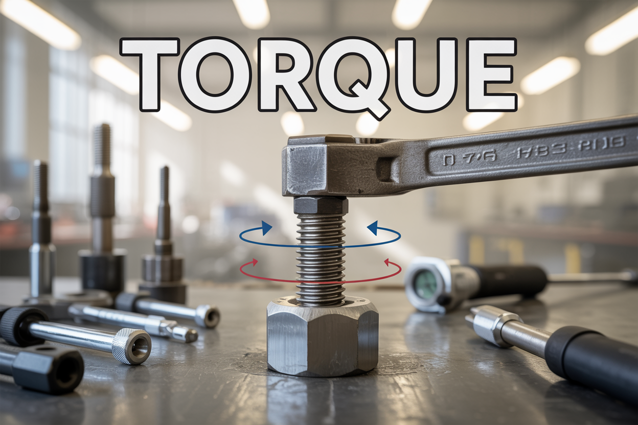
Torque is the twisting force that makes everything rotate around us – from car engines powering down the highway to robotic arms assembling electronics with precision. This fundamental physics concept is essential for engineers, mechanics, automotive enthusiasts, and anyone working with rotating machinery or robotics.
Understanding torque helps you make better decisions about vehicle performance, troubleshoot mechanical problems, and design systems that harness rotational power effectively. Whether you’re comparing car specs, working on industrial equipment, or developing robotic applications, torque knowledge gives you insight into how rotational forces create motion and power.
We’ll explore the fundamental physics behind torque and how force creates rotational motion. You’ll learn about the different types of torque applications, from automotive engines that deliver acceleration and towing power to industrial robots that require precise force control for delicate assembly work. Finally, we’ll cover the practical tools and measurement techniques used to quantify and control torque in real-world applications.
Understanding Torque Fundamentals
Understanding Torque Fundamentals
Definition and Basic Principles of Rotational Force
Torque is the measure of the force that can cause an object to rotate about an axis. Just as force causes an object to accelerate in linear kinematics, torque is what causes angular acceleration. Hence, torque can be defined as the rotational equivalent of linear force. The straight line about which the object rotates is called the axis of rotation.
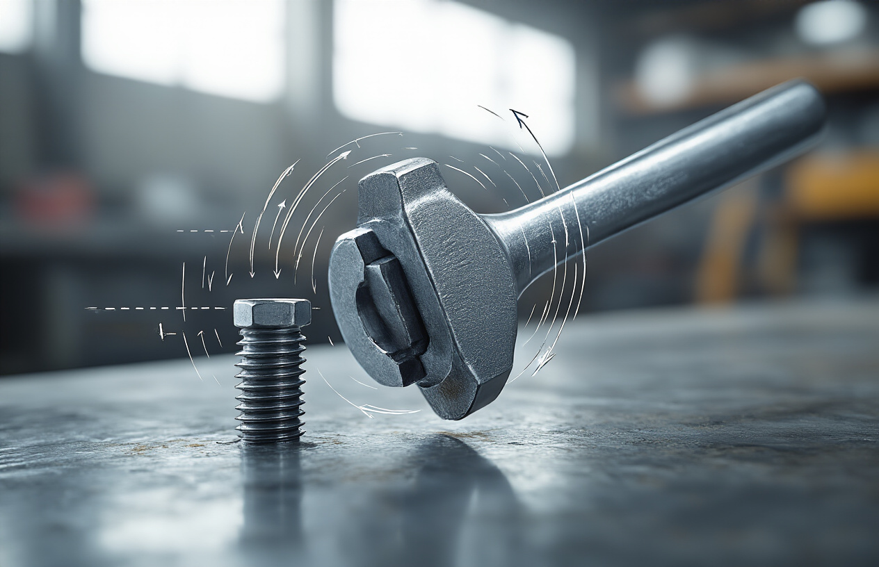
In physics, torque is simply the tendency of a force to turn or twist an object. Different terminologies such as moment or moment of force are interchangeably used to describe torque. The distance of the point of application of force from the axis of rotation is sometimes called the moment arm or lever arm.
To understand torque fundamentally, consider that when forces are applied to a body, even if the net force is zero and the body is in translational equilibrium, it may still tend to rotate. This turning effect produced by force is what we call torque or moment of force.
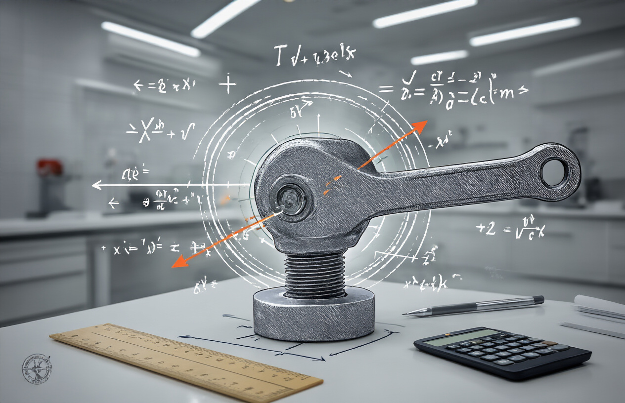
Mathematical Formula and Key Components
The mathematical representation of torque depends on three key quantities: the force applied, the lever arm vector connecting the point about which torque is measured to the point of force application, and the angle between the force and lever arm vectors.
Mathematically, torque is represented as:
τ = F × r × sin θ
Where:
- τ (tau) is the torque
- F is the magnitude of the applied force
- r is the length of the lever arm (distance from axis of rotation to point of force application)
- θ is the angle between the force vector and the lever arm
The above equation can also be represented as the vector product of force and position vector:
τ⃗ = r⃗ × F⃗
Since this is a vector product, torque is also a vector quantity. The direction of the torque can be determined using the right-hand grip rule: if the fingers of the right hand are curled from the direction of the lever arm to the direction of the force, then the thumb points in the direction of the torque.
How Torque Differs from Linear Force
While linear force causes translational motion along a straight path, torque produces rotational motion around an axis. The fundamental difference lies in their effects on object motion:
- Linear Force: Produces or tends to produce motion along a line, causing linear acceleration
- Torque: Produces or tends to produce torsion around an axis, causing angular acceleration
Just as a linear force is a push or pull applied to a body, torque can be thought of as a twist applied to an object with respect to a chosen point. For example, driving a screw uses torque to force it into an object, which is applied by the screwdriver rotating around its axis.
Any force directed parallel to the particle’s position vector does not produce torque, as the sine of the angle between them would be zero. Only the perpendicular component of force contributes to torque production.
Units of Measurement and Conversions
The SI unit for torque is the newton-metre (N⋅m). This unit has the same dimensions as energy (joules), but torque and energy represent fundamentally different physical quantities. While energy is a scalar quantity, torque is a vector quantity, which is why the joule is never used for expressing torque despite the dimensional equivalence.
In imperial units, torque is commonly measured in:
- Pound-foot (lbf⋅ft) for larger values
- Pound-inch (lbf⋅in) for smaller values
In the US, torque is most commonly referred to as:
- Foot-pound (ft-lb or lb-ft)
- Inch-pound (in-lb)
Common Conversion Factors
When converting between different measurement systems, practitioners must be careful to distinguish torque units from energy units through context and proper notation. The hyphen placement in abbreviations helps indicate that these refer to torque rather than energy measurements.
For rotational applications, conversion factors may be necessary when using different units of rotational speed, requiring multiplication by 2π radians per revolution when converting from revolutions per minute to radians per second.
Types and Classifications of Torque
Types and Classifications of Torque
Static vs Dynamic Torque Applications
Understanding torque requires recognizing its two fundamental classifications: static and dynamic applications. Static torque, commonly referred to as holding torque, represents the maximum torque that can be resisted when a shaft remains stationary while the system is energized. This type of torque is crucial for applications requiring precise positioning and load holding capabilities without any movement.
In contrast, dynamic torque refers to the torque generated when a system is in motion, varying with speed and representing the load-carrying capacity during rotation. Dynamic torque demonstrates a critical characteristic: it decreases as stepping frequency increases due to the inductance of windings, which limits stepping rates and reduces magnetic field strength at higher speeds.
The measurement conditions for these torque types differ significantly. Static torque is measured when the system is energized but not rotating, tested by gradually applying load until position is lost. Dynamic torque requires measurement during rotation at various speeds to record output characteristics across different operating conditions.
Speed dependency creates a fundamental distinction between these classifications. Static torque remains constant, depending solely on design parameters and supplied current. Dynamic torque, however, shows inverse relationship with speed due to inductance, back-EMF, and limited current rise in windings.
| Torque Type | Measurement Condition | Speed Dependency | Primary Applications |
|---|---|---|---|
| Static | Energized, not rotating | Constant | Positioning systems, holding applications |
| Dynamic | During rotation | Decreases with speed | Conveyor systems, moving operations |
Historical Terminology and Regional Variations
The terminology surrounding torque has evolved through engineering history, with static torque frequently referenced as “holding torque” in motor applications. This historical naming convention reflects the fundamental purpose of static torque in maintaining position under load conditions.
Regional engineering practices have contributed to variations in torque classification terminology, though the underlying principles remain consistent across different geographical applications. The distinction between static and dynamic applications has been universally adopted in professional engineering contexts.
Torque as Moment of Force in Engineering
In engineering applications, torque functions as the moment of force that enables rotational movement and positional accuracy. This moment of force directly influences performance and reliability in precision applications, making torque selection critical for system design.
Torque measurement utilizes professional instruments that employ strain gauges applied to rotating shafts or axles. These strain gauge assemblies, while compact, provide powerful measurement capabilities essential for torque quantification in both static and dynamic conditions.
The working principles distinguish static and dynamic torque measurement approaches. Static torque sensors convert strain generated by force into electrical signals with linear relationships, while dynamic torque sensors measure electrical signals from elastic shaft torsion, forming strain bridges through electrical measuring technology to provide proportional frequency signals after amplification.
Both dynamic and static sensors can measure static working torque, but dynamic working torque requires specialized dynamic sensors capable of handling the complexities of rotational measurement during operation.
Mathematical Relationships and Physics
Mathematical Relationships and Physics
Cross Product Definition and Vector Properties
Torque is fundamentally defined as the cross product between the position vector and the force vector: τ = r × F = rF sin(θ), where θ is the angle between the vectors. The cross product produces a third vector perpendicular to the plane containing both the position and force vectors, with its direction determined by the right-hand rule.
When applying the right-hand rule, fingers point in the direction of the position vector r, curl toward the force vector F, and the thumb indicates the torque vector’s direction. This mathematical operation ensures that torque is a vector quantity with both magnitude and direction, distinguishing it from scalar quantities.
The cross product can be expressed in component form:
- τₓ = AᵧBᵧ – AᵧBᵧ
- τᵧ = AᵧBₓ – AₓBᵧ
- τᵧ = AₓBᵧ – AᵧBₓ
A crucial property is that A × B = -B × A, meaning the order of vectors matters. Only the perpendicular component of force contributes to torque, as forces acting parallel to the position vector produce zero torque since sin(0°) = 0.
Relationship with Angular Momentum and Velocity
The relationship between torque and angular momentum forms one of physics’ fundamental principles: τ = dL/dt, where L represents angular momentum. This equation establishes that torque equals the time rate of change of angular momentum, making it the rotational analog of Newton’s second law.
For a point particle, angular momentum is defined as L = r × p, where p is linear momentum. Taking the time derivative:
dL/dt = d/dt(r × p) = (dr/dt × p) + (r × dp/dt)
Since dr/dt is velocity v, and dp/dt is force F, and knowing that v × p = 0 (velocity and momentum are parallel), the equation simplifies to:
τ = r × F
This derivation proves the equivalence between the cross product definition and the angular momentum relationship. For rotating rigid bodies, this extends to τ = Iα, where I is moment of inertia and α is angular acceleration, connecting torque directly to rotational motion parameters.
Connection to Power and Energy Equations
Torque’s relationship with power and energy reveals important mechanical principles. Power in rotational systems is given by P = τ · ω, where ω is angular velocity and the dot represents the scalar product. This equation parallels linear power (P = F · v) and shows how rotational power depends on both torque magnitude and rotational speed.
The work done by torque through angular displacement follows: W = ∫τ dθ, where θ represents angular position. For constant torque, this simplifies to W = τ(θ₂ – θ₁). This work directly relates to changes in rotational kinetic energy:
W = ΔEᵣ = ½I(ω₂² – ω₁²)
The infinitesimal work relationship dW = τ dθ connects linear and angular displacement through ds = r dθ, allowing derivation of the power equation. Importantly, power depends only on instantaneous angular speed, not whether that speed increases, decreases, or remains constant during torque application.
Principle of Moments and Equilibrium
The principle of moments, also known as Varignon’s theorem, states that the net torque about any point equals the sum of individual torques: Στ = τ₁ + τ₂ + … + τₙ. This principle enables complex force analysis by breaking systems into manageable components.
For rotational equilibrium, the sum of all torques must equal zero: Στ = 0. This condition, combined with force equilibrium (ΣF = 0), determines static equilibrium in mechanical systems. In two-dimensional problems, three equations govern equilibrium: ΣFₓ = 0, ΣFᵧ = 0, and Στ = 0.
When net force on a system is zero, torque measured from any point remains identical. However, if net force is non-zero, torque measurements from different reference points will vary according to the relationship between those points and the force application locations. This principle proves essential for analyzing complex mechanical systems, from simple levers to sophisticated robotic mechanisms, where multiple forces act simultaneously at different points.
Torque in Automotive Applications
Torque in Automotive Applications
Engine Torque Generation and Performance
Engine torque represents the rotational force that translates directly into a vehicle’s acceleration and overall performance capability. In internal combustion engines, torque is generated through the four-cycle process where air and fuel are brought into cylinders, compressed, ignited, and expelled. The peak torque occurs at the engine speed where the most complete and efficient combustion takes place, creating the highest cylinder pressures and maximum rotational force.
The torque generation process varies significantly across different engine types. Traditional naturally aspirated engines typically produce their peak torque in the middle of their rev range, while modern turbocharged engines deliver sustained torque plateaus across wider rpm ranges. This broad torque delivery makes turbocharged vehicles feel more responsive in everyday driving situations. Electric vehicles represent a revolutionary approach to torque generation, producing maximum torque instantly from 0 rpm without the need to build engine speed, resulting in immediate acceleration response.
Impact on Acceleration and Towing Capacity
Torque plays the primary role in determining how quickly a vehicle accelerates from a standstill and its ability to handle heavy loads. When you experience that push-back sensation in your seat during rapid acceleration, that’s torque at work. Higher torque enables vehicles to launch more aggressively from traffic lights and provides the pulling power necessary for demanding applications.
For towing applications, torque becomes absolutely crucial. Vehicles designed for heavy-duty work, such as diesel trucks, prioritize high torque output over peak horsepower. The 2023 Ford F-150 with its 3.5-liter PowerBoost Full Hybrid V6 engine produces 570 lb-ft of torque, enabling substantial towing and payload capabilities despite producing “only” 450 horsepower. This demonstrates how torque directly correlates with a vehicle’s ability to move heavy loads and perform work-oriented tasks.
The relationship between torque and acceleration becomes particularly evident in different driving scenarios. For city driving and suburban commuting, good low- to mid-range torque proves more beneficial than peak horsepower for responsive starts and smooth traffic navigation. Off-roading situations require substantial low-speed torque for crawling over obstacles and maintaining momentum on challenging terrain.
Torque Curves and Speed Relationships
The torque curve represents how an engine’s torque output varies across its operating speed range, fundamentally defining the engine’s character and driving experience. Below the peak torque point, pistons don’t move with sufficient velocity to draw maximum air into the cylinders, limiting fuel delivery and resulting in lower cylinder pressures. As engine speed increases beyond the peak torque point, faster-moving air encounters increased friction in the intake tract, and there’s insufficient time to complete the combustion cycle efficiently.
Different engine configurations produce distinctly shaped torque curves. Economy cars often exhibit torque that peaks in the middle of the rev range before dropping quickly, creating a narrow power band. Turbocharged engines can maintain relatively flat torque curves, delivering consistent pulling power across broader speed ranges. Sports car engines might build torque steadily toward high-rpm climaxes, rewarding drivers who keep engines in upper rev ranges.
Electric vehicles fundamentally alter the torque-speed relationship by delivering maximum torque immediately upon acceleration, maintaining consistent power delivery across their entire operating range. This instant torque availability creates a driving experience that feels dramatically different from traditional internal combustion engines, providing immediate response without lag or the need to build engine speed.
Transmission Systems and Torque Multiplication
Transmission systems serve as torque multipliers, taking the engine’s rotational force and amplifying it through gear reduction ratios before delivering it to the wheels. This multiplication effect explains why wheel torque measurements always result in larger numbers than engine torque figures. The torque travels from the engine through the transmission, then via driveshafts to the wheels, where it becomes the force that propels the vehicle forward.
Understanding torque multiplication becomes crucial when evaluating vehicle specifications. Some manufacturers have begun advertising wheel torque figures rather than engine torque, creating misleadingly large numbers. The GMC Hummer EV’s claimed 11,500 lb-ft represents wheel torque, while traditional automotive specifications quote engine output. Using the same measurement standard, a Dodge Charger SRT Hellcat would claim 8,021 lb-ft instead of its actual 650 lb-ft engine torque rating.
The transmission’s role in torque delivery affects how vehicles perform across different speed ranges. Lower gears provide maximum torque multiplication for initial acceleration and heavy-load situations, while higher gears reduce torque multiplication in favor of higher speeds and improved fuel efficiency. This relationship between transmission gearing and torque delivery explains why manual transmissions allow drivers to optimize engine torque for specific driving conditions by selecting appropriate gear ratios.
Industrial and Robotic Applications

Industrial and Robotic Applications
Precision Control in Manufacturing
Force/Torque integration represents a revolutionary advancement in industrial robotics, enabling robots to perform tasks that require precise control of the contact forces and torques between the robot and the environment. This sophisticated technique proves invaluable for assembly operations, manipulation tasks, polishing, grinding, and deburring applications where traditional position-based control falls short.
The fundamental approach involves utilizing sensors that measure the six components of the force and torque vector at the robot’s end-effector. This sensor data is then processed to adjust the robot’s motion and impedance parameters dynamically, achieving the desired Force/Torque profile throughout the manufacturing process. Various implementation methods exist, including hybrid position/force control, impedance control, and admittance control, each tailored to specific manufacturing requirements.
Joint Movement and Stability Systems
Now that we understand the basic principles, the integration of Force/Torque systems significantly enhances joint movement precision and overall system stability. The hardware and software combination allows robots to make minute path adjustments in real-time, enabling them to adapt their path and orientation when performing designated applications. This capability is particularly crucial in manufacturing environments where dimensional tolerances are tight and consistency is paramount.
The system’s ability to provide dynamic feedback ensures that robotic movements remain stable even when encountering unexpected variations in workpiece geometry or material properties. This adaptability transforms rigid automation systems into flexible, responsive manufacturing solutions.
Force-Torque Sensors for Real-Time Feedback
With this enhanced control capability in mind, Force/Torque sensors serve as the critical sensory input that gives robots a sophisticated ‘sense of touch.’ The OptoForce Six-Axis Force/Torque Sensor exemplifies this technology by measuring force and torque components in X, Y, and Z coordinates at the tool or part interface at the end of the robot arm.
Real-time monitoring capabilities display all specific forces and torques experienced by the sensor through graphical representations on the robot’s pendant HMI. This immediate feedback system enables operators to visualize the interaction forces and make informed decisions about process parameters. When forces exceed predetermined specifications, the system automatically stops and triggers alarms, providing essential protection for both equipment and workpieces.
Safety and Interaction Capabilities
Previously established feedback systems contribute significantly to enhanced safety protocols in industrial environments. The ability to monitor and respond to force variations in real-time creates inherent safety mechanisms that protect both human operators and expensive manufacturing equipment. When unexpected resistance or force spikes occur, the system can immediately halt operations, preventing damage and ensuring workplace safety.
This force-sensitive capability is especially valuable during troubleshooting applications, where understanding the specific forces and torques helps identify process irregularities or equipment malfunctions. Before full implementation, proof-of-concept evaluations can determine the feasibility of Force/Torque control for specific applications, ensuring optimal integration into existing manufacturing processes while maintaining the highest safety standards.
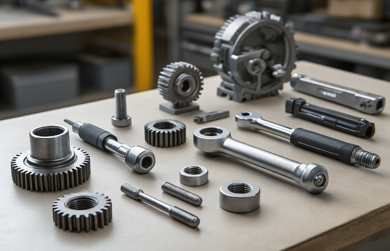
Practical Tools and Measurement

Practical Tools and Measurement
Torque Wrenches and Precision Applications
Digital torque wrenches represent the pinnacle of precision torque application and measurement. These sophisticated instruments offer accuracy levels of ±1% of actual reading, with capacities ranging from compact 106 lbf-in units for limited access applications to heavy-duty models reaching 1460 lb-ft capacity. The digital displays provide real-time torque readings in multiple units, including oz-in, lb-in, lb-ft, N-m, cN-m, kgf-cm, gf-cm, and kgf-m.
For production environments where over-torquing must be prevented, cam-over torque wrenches automatically disengage when preset torque values are reached. These tools feature capacities up to 90 lb-ft and are available in 1/4″, 3/8″, and 1/2″ drive configurations. Break-over torque wrenches provide similar protection, with models ranging from miniature 1 oz-in units to robust 1770 lbf-in capacity wrenches.
Advanced digital torque wrenches incorporate USB data output capabilities, enabling comprehensive data collection and analysis. These precision instruments often include programmable target torque set-points, with some models offering up to 9 different preset values. The integration of angle measurement capabilities allows for torque-plus-angle tightening strategies, critical in automotive and aerospace applications.
Dynamometers for Performance Testing
High-precision torque testers serve as the foundation for tool verification and calibration across industrial applications. Multi-channel torque testers accommodate power drivers and wrenches with accuracy levels of 0.5% of reading across 18 ranges extending up to 5000 lb-ft. These sophisticated instruments display measurements in eight different units and feature high-speed 7,000 Hz sampling rates to accurately capture peak torque values.
Impact wrench torque test systems represent specialized dynamometer applications, with capacities reaching 5000 lb-ft for pneumatic tools and up to 50,000 lb-ft for hydraulic wrench testing. Run-down fixtures and joint simulators are essential components for accurate power tool measurement, providing consistent loading conditions that simulate real-world fastening scenarios.
Digital torque analyzers with built-in transducers enable bi-directional testing and calibration of various torque tools. These instruments feature capacities up to 738 lb-ft and incorporate touch-screen interfaces for intuitive operation. For rotating torque measurement applications, specialized transducers accommodate ranges from 1 lb-in to 1500 lb-ft, suitable for both hand tools and power tool applications.
Conversion Between Different Unit Systems
Professional torque measurement requires seamless conversion between multiple unit systems to accommodate global manufacturing standards. Modern digital torque instruments typically display measurements in eight primary units: oz-in (ounce-inches), lb-in (pound-inches), lb-ft (pound-feet), N-m (Newton-meters), cN-m (centi-Newton-meters), kgf-cm (kilogram-force-centimeters), gf-cm (gram-force-centimeters), and kgf-m (kilogram-force-meters).
The conversion capabilities built into contemporary torque measurement systems eliminate manual calculation errors and ensure consistency across different regional standards. For instance, torque testers can simultaneously display readings in Imperial units for domestic applications while providing metric equivalents for international compliance. This multi-unit functionality proves particularly valuable in automotive manufacturing, where specifications may originate from different global engineering centers.
Advanced torque measurement systems incorporate programmable unit selection, allowing operators to customize displays based on specific application requirements. The ability to switch between fine-resolution units (such as cN-m) for precision applications and larger units (like lb-ft) for heavy-duty applications ensures optimal readability and accuracy across the full measurement range.
Real-World Examples and Calculations
Practical torque applications demonstrate the critical importance of precise measurement and control. In cap torque testing applications, digital instruments with capacities up to 90 lb-in provide memory storage for 1000 measurement values, enabling comprehensive quality control documentation. These systems incorporate Hi/Go/Lo limit indicators with LED displays for immediate pass/fail identification during production testing.
Electric screwdriver verification requires specialized torque testers with ranges up to 130 lb-in, featuring USB data output for statistical process control integration. The measurement accuracy of ±0.5% full scale from 20% to 100% of capacity ensures reliable calibration of production tools. For miniature applications, handheld digital torque gauges with 1000-data memory capabilities provide portable measurement solutions for field verification.
Torque calibration arms and torque wheels serve as reference standards for verifying measurement equipment accuracy. These precision instruments, supplied with NIST traceable calibration certificates, enable periodic verification of torque testers and transducers. The modular design of torque test stands accommodates various tool configurations, while angle indication features support torque-plus-angle measurement protocols essential in critical fastening applications.

From understanding the fundamental physics of rotational force to exploring its critical applications in automotive and industrial systems, torque emerges as one of the most essential concepts in modern engineering. Whether it’s the twisting force that accelerates your car, the precise control needed for robotic assembly lines, or the measurement tools that ensure proper bolt tightening, torque influences virtually every aspect of mechanical motion around us. The mathematical relationships between force, distance, and angular momentum provide the foundation for designing everything from simple wrenches to complex automated manufacturing systems.
As technology continues to advance, the importance of torque control and measurement will only grow. In robotics, precise torque sensors enable delicate manipulation and safe human-robot interaction. In automotive applications, understanding torque curves helps optimize both performance and fuel efficiency. For engineers and technicians working with any rotating machinery, mastering torque principles—from basic calculations to practical measurement techniques—remains fundamental to creating reliable, efficient systems that power our modern world.